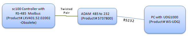
UDG1000 can read data from an sc100 via Modbus RTU/ASCII. In order for UDG1000 to read data from the sc100 it must be connected to the serial port:
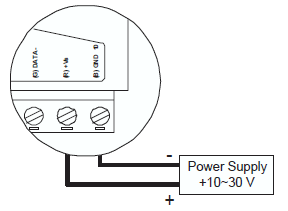
The twisted pair wire must connect the Ext Network Connection to the ADAMtm-4520 converter. Open the sc100 and looking at the inside door you will see the Ext. Network Connection:
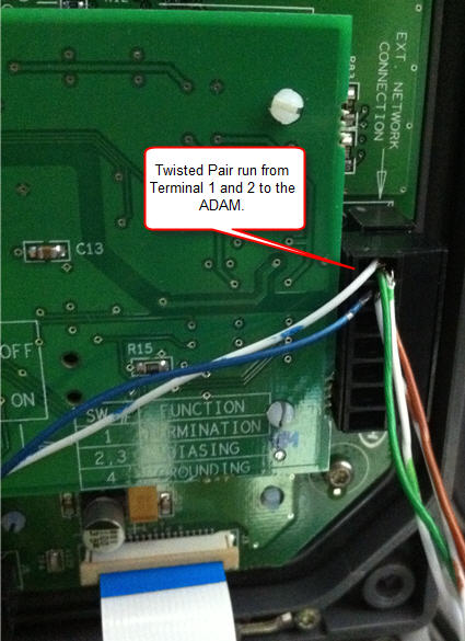
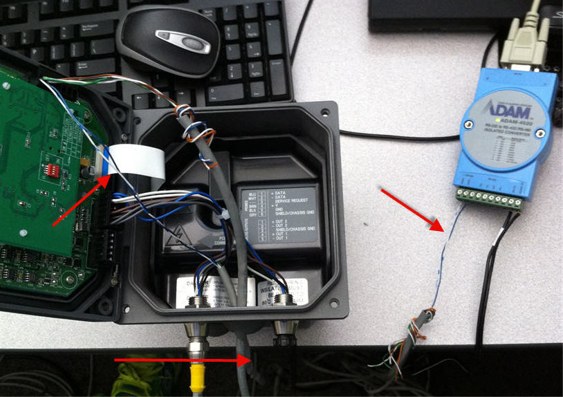
Notice white goes to 1 on Ext Network Connection Terminal and connects to 1 (RS-485 Data +) on Adam. Blue wire goes from 2 on Ext Network Connection Terminal and connects to 2 (RS-485 -) on Adam.
Connect the power to the ADAM. See ADAM-4510_4510S_4520_Startup_ed4.pdf for more information.
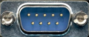
From the Adam, you connect the RS-232 cable (tan cable in above picture) to the serial port on your PC.
You may need to install the ADAM drivers (dll) if communication is not working. We are not sure if the driver is required, however if you are having trouble communicating to the ADAM/sc100 it is sugguested that you install the drivers by downloading the attached ADAM_DLL.ZIP.
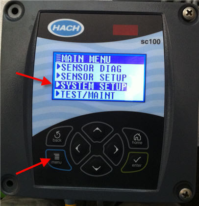
Once you have the wiring complete, the next step is to setup the communication settings on the sc100 and UDG1000. On the sc100 go to Menu>System Setup>Network Setup. Set/Note the Baud Rate, Mode, Stop Bits, and data order.
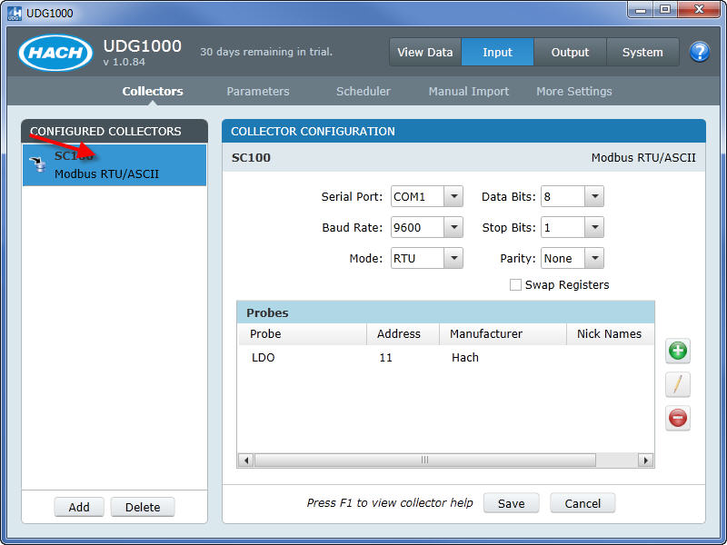
UDG1000 Setup screen. Set the Baud Rate, Mode, Data Bits, Stop Bits to match your sc100 settings. Parity should be set to None for the sc100.
NOTE: Swap Registers needs to be set to match the sc100 Data Order Setting. However, during tested it appears that if the sc100 is set to Swapped the UDG1000 Swap Registers should NOT be checked. If the Swap Registers/Data Order setting is not set correctly, UDG1000 will retrieve data but it will be random values (i.e. negative numbers, very large numbers). If you are seeing numbers like this, simply change your Swap Registers setting, go to View Data and see if the proper data is displayed.
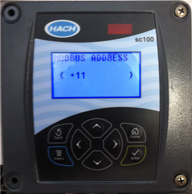
Next set/note your Modbus Addresses on the sc100. You will have a seperate modbus address for the sc100 controller and each of the probes. Go to Menu>System Setup>Network Setup>Modbus Address. The sc100 will list the controller and probes:
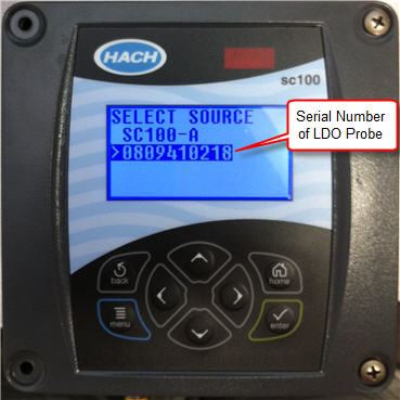
In this example the LDO Probe has a Modbus address of 11. NOTE: The last digit of the Modbus address will blink on the sc100 indicating you can change that number. Please be aware that the last (blinking) digit is part of the modbus address: