Direct Measurement of the Interfacial Settling Velocity
This procedure is the standard for determination of activated sludge interface settling velocity. This process is used for measuring activated sludge settling velocity.
You will need the following materials to carry out this procedure:
-
Clear column (at least two inches, preferably eight, in diameter) with scale marked in inches or 2000 ml (minimum) graduated cylinder
-
MLSS at aeration basin and recycle concentrations
-
Secondary clarifier effluent (dilution water)
-
Stirring rod
-
Stopwatch or watch with second hand and linear graph paper
The best column for performing this procedure is at least eight inches in diameter and three feet tall. For many industrial wastes, this size is mandatory. Municipal wastes can use the graduated cylinder or two inches diameter clear column. The eight inch column will give a good approximation to the settling conditions found in real clarifiers. Make sure that the base is sturdy enough to support a column of water and that the seal of the base to the column is water tight under the same conditions.
The side of the column should be marked in inches, with the zero (0) mark near the top of the column, to allow easy measurement of the interfacial settling velocity. If this cylinder is not available, the largest graduated cylinder should be used. A secondary scale of inches should be marked on the side of the column to allow easy measurement if it is not convenient to convert from the standard ml scale.
Dilutions
Sludge from the aeration basin and the recycle (return) flow from the secondary clarifier to the aeration basin must be collected so that the settling velocities of different concentrations can be calculated. Dilutions are made using secondary clarifier effluent (prior to chlorination). If the secondary effluent is cloudy, allow any particulate matter to settle and use the supernatant. The following are suggested MLSS concentrations for the determination of settling velocities:
- 50% aeration basin MLSS
- 75% aeration basin MLSS
- Actual aeration basin MLSS
- 75% recycle concentration
- Actual recycle concentration
Settling velocities for additional concentrations may have to be determined if flux curves prepared from the above concentrations do not give accurate indications of clarifier performance.
When making dilutions, always put the clarifier effluent in the column first and then add sludge on top. Ensure that the contents are at a uniform concentration by gently stirring prior to beginning the measurement of interfacial settling height. It is essential that the integrity of the floc is preserved.
Procedure: Full Strength Mixed Liquor
Follow these steps for taking Full Strength Mixed Liquor samples:
- Tilt column at an angle so the mixed liquor can be poured down the side of the column.
- Slowly pour the mixed liquor in the column until it nearly reaches the zero mark.
- Stand the column upright and continue filling to the zero mark.
- Gently stir the contents to ensure a uniform concentration. Be sure not to destroy the floc.
- Start the stopwatch.
- Record the interface height with respect to time. Use the Solids Flux Field Data Sheet template found in the Custom Data Entry Process Modeling Templates.
- It is good practice to indicate any visual settling characteristics, such as pinfloc or bulking sludge, on the data sheet. This can provide a reference in case questions arise concerning the validity of a specific flux curve.
Procedure: Dilutions
Follow these steps to prepare dilutions from the samples taken:
- Fill to the appropriate mark with clarifier effluent.
- Tilt the column and slowly pour either mixed liquor or return sludge down the side of the column.
- Stand the column upright and continue filling to the zero mark with solids.
- Gently stir the contents to ensure a uniform concentration. Be sure not to destroy the floc.
- Start the stopwatch.
- Record the interface height with respect to time. Use the Solids Flux Field Data Sheet template found in the Custom Data Entry Process Modeling Templates.
Analysis: Determine Settling Velocity
The Solids Flux Field Data Sheet template performs the analysis for you. However, the following section can be used to better understand the steps on the form.
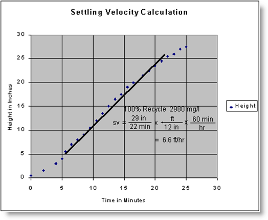
- Plot the recorded settling height (in inches from the zero mark) on the y-axis and the associated time in minutes on the x-axis.
- Draw a straight line through the linear portion of the curve. An example of the graphical procedure is shown below.
- Calculate the slope of the line (the negative of the settling velocity) in inches/minute, for the particular solids concentration. Multiply this result by (5.0) to get the velocity in feet/hour.
- Use the Add New Flux Curves option discussed in Chapter Seven to calculate a new flux curve from the collected settling velocity data.
NOTE: The solids concentration must be entered in units of mg/l and the settling velocity must be in units of feet/hour.
Example of Graphical Procedure to Determine Settling Velocity